Sunday, July 15, 2012

Botched quarter panel skin repair

I made good work of everything detailed in this entry, completing it all in three days after manning up and taking the heat in the shop for long days.  In an earlier entry I wrote about replacing a quarter skin.  The repair went well except for major warpage I encountered along the weld, and it was due to a new method I was trying.  Countless (or so it seemed) hours of on-dolly hammering to stretch was to no avail but with the warpage as pronounced as it was, there was absolutely no way it would be able to stay in this form if I wanted a straight side.

The Problem
The problem was due to how I made the welds.  I would make single spaced out tacks and let it cool naturally.  However, for the next round of tacks, I then placed the next tack directly next to the old one rather than splitting the difference between two old tacks (this latter method is how I've done all my welds up to this time).  This new method is pictured in the original entry I linked above.  It made a nice pretty weld but really affected the way the metal was pulled with each new tack. 

The Fix
By cutting the weld back open, I should be able to relax the metal and do some additional stretching.  Then reweld back shut, but splitting the difference in distance between tacks rather than laying the new tack next to the old as I did before.  Second, constantly stretching the weld area after each round of tacks should help me keep ahead of any extreme shrinkage and distortion.

I first experimented with making a ~6 inch opening of the old weld.  I found it works best to open longer sections at a time because weird stuff happens at each end of the cut.

Putting the welds back in show the best way to tack it back shut, splitting the distance between welds, as opposed to spacing tack welds out initially, then putting all new tacks next to the original tacks instead of between them.


The fix was a great success and the horrible warpage I had before is now gone.  The difference between the side of the panel is night and day.  It's puckered in giving me room to fill.  This will be a nice panel to work now.

While I was at it, I had this original corner bracket in the rear.  It was bugging me because it was all chewed up and didn't look good.  I had an extra new one so I decided to just replace it.

So I cut the old one out, carefully removing the spot welds...

And got the new one welded in place.

After grinding down the welds and cleaning it up, this is the final repair.

I prepped the panel and shot it with SPI epoxy.  I prefer to do my filler work over epoxy for maximum corrosion protection.  Filler work will begin the next day...

Saturday, July 7, 2012

Slick Sand: Sprayable polyester surfacer/primer

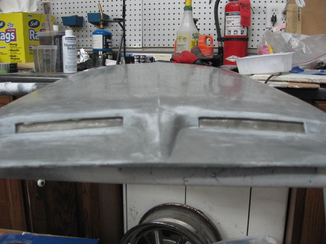
Today I'm going to start detailing the beginnings of my final blocking, for which I enlisted the help of Evercoat Slick Sand.  But first, everything begins with finishing up the hood scoop from where I most recently left off...

I decided I did not want the turn signal indicators in the hood scoop so...

I roughed up the edges of the fiberglass with 180

Then laid down fiberglass cloth with fiberglass resin, using a simple Bondo fiberglass patch kit that can be had anywhere (even Wal*Mart) for $20.  It's cheaper than buying the components on their own and having a lot of material left over in the end.

This is with the cured cloth/resin.

I then skimmed the opening with Evercoat fiberglass filler.

And skimmed that with Evercoat EZ Sand 2k glazing putty for a smooth finish.

The next step was to spray with Epoxy, then Slick Sand.  I bought this gun from TCP Global for about $45...with a 2.5 mm tip it's nothing short of a cannon.  It is fantastic quality and shoots the Slick Sand unreduced perfectly.

After the fiberglass had UV cured by sitting outside for 5 days, I shot it with Epoxy.

And there is no trace of a hole ever being present in the turn signal openings.  Any tiny imperfections will get covered up by the Slick Sand.

I then shot the scoop with 2-3 coats of Ever Coat Slick Sand, an extremely high build primer/surfacer.  It's actually sprayable polyester filler.  The hoodscoop was very wavy since it is a fiberglass part, and I wanted to do an experiment to see if I could completely block out the waves using only Slick Sand and no skim coat of filler.  Truth be told, I didn't think it would happen.

Tape along the center ridge line and block up to this; it will keep the center ridge straight and sharp, and prevent reshaping of the ridge line.  The Slick Sand dries quite hard and is difficult to initially block.  In the end I have found that starting with 120 works great to cut, then 220 to remove the 120 scratches.  To my surprise, after blocking the scoop down, and then shooting with another 2 coats, the entire scoop blocked completely flat without the use of any skim coating filler.
Along with the hood scoop, I also shot the roof, driver's side door, and top of the trunk with several coats of Slick Sand, usually shooting 2 at a time, blocking, then shooting more.  Here are some tips I have either read or learned on my own:

  1.  Buy a cheap gun to shoot Slick Sand.  That way if it sets up in your gun, you're not out your good gun.
  2. Buy a gun with a large enough tip.  It seems somewhat defeating the point if you buy a high build product, only to be thinned out so it doesn't build as well.   I think Ever Coat recommends at least a 2.0 mm tip.  My 2.5 mm tip was plenty sufficient.
  3. Do not leave the Slick Sand in your gun for more than 30 minutes or it risks setting up.  I did not mix more than I could shoot in 30 minutes.  At the moment I added the hardener, I started the timer, which would include mixing, spraying, and flash times.
  4. Do not use an in-gun strainer, or even filter the product as it pours into the gun.  The gun I bought had an internal strainer and the Slick Sand basically spit and sprayed poorly.  I removed that and was back in business.  I eventually even stopped filtering it as I poured it into the gun because it would take so long to drain through my filter.  Even unfiltered I had no hitches when spraying.
  5. Start cutting with 120, then move to 180 or 220 for final blocking.  Once the initial layer is off, it sands very nicely.  It will spray on with lots of peel so the initial blocking seems to bounce right over the top.
  6. A lot does not go a very long way.  I mix up half a quart at a time.  I pour out 16 ounces, and then add half a tube of hardener (11 ml, to be exact) to the 16 ounces.  The tube of hardener has graduations on the side so you can see how much to add.  One gallon comes with four tubes of hardener; one tube per quart.  Mix well (it greatly thickens upon adding the hardener) then spray, allowing for adequate flash.  Half a quart basically allowed me to shoot one coat on my hood scoop, door, roof, and trunk lid before it was all gone.  I then poured some lacquer thinner in the cup, swished around, and sprayed the lacquer thinner out to get everything out of the gun's system, then mixed up  more and sprayed a second round.  In  doing this I never end up wasting any and I don't risk it setting around too long and setting up in my gun.
  7. Spray when it's cool outside to keep it from setting up too fast.  I sprayed early on when it was 60's and 70's out.  It's been over 100 consistently for the last week or two (108F yesterday) and I'm glad I got most of it out of the way.
  8. Mask off anything you don't want overspray on WELL.  This is definitely overspray you don't want to have to remove.  Additionally, it makes the floor sticky so I laid a blue tarp on the floor and painted over this.  I had read about this ahead of time so did not have to end up with a sticky garage floor.
All in all, I have used 3/4 gallon between the roof, trunk, one quarter, one door, hood, and hood scoop.  The hood is final blocked, as is the door, roof, and trunk.  The quarter is close but will probably require another coat or two.  The moral of the story is it will probably require 2 gallons to do an entire car.  I still have another quarter to do.  I may have to end up getting another quart.

Final thoughs on Slick Sand:  Amazing build and sands great once you've cut off the top layer.  You can keep blocking and blocking and blocking before you see signs of breaking through.  The advantage of this is you can keep blocking until the last of that guide coat is gone and still have room to shoot another layer of guide coat and block it again.  It did amazing things with my quarter that definitely had a few spots my hand could feel after my metal working (and filler work), which was probably sub par at best, I admit.  I was counting on the Slick Sand to be my crutch and it really was.
Thursday, April 5, 2012

Bolting on a hood scoop

Having a hood scoop on my car is something I've always dreamed of, and certainly one of the first things that went on my list of 'must haves' when I originally bought this Mustang.  Going on four years now I've dreamed of what my scooped hood would look like, so while CJ's had this Dynacorn 69 Mach 1 hood scoop on sale for 20% off, I jumped on the opportunity to finally make it happen.  After all, the timing was growing essential since I am currently doing the body work on the hood.While this hood scoop was originally for 69 Mach 1's, it is essentially the same scoop you'd find on a 68 428 Cobra jet, though the bolt holes are different.  Nevertheless I have a friend who installed one of these scoops on his 67 as well, and the scoop will fit on just fine.    It was nice to finally do a 'fun' thing to the restoration.  You all know what it's like; you have the the list of absolute essentials you have to do....take off old undercoating, add new caulk, or in my case, day in and day out of  body work, applying filler, and sanding filler and primer.  And then you have that list of the really 'fun' things you want to do...the often 'non-essentials' to performance of the car, and serve no other purpose other than to make the ride look neat.  I'm rambling now so I'm going to stop.

I bought this hood scoop template on Ebay for a grand total of $3 shipped.

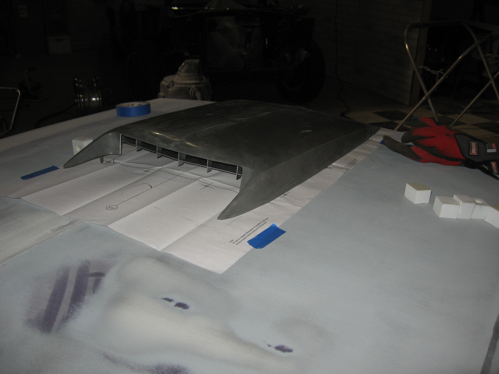
Rather than blindly sticking the template down and drilling holes, I did a test to see how well they matched up with the bolts on my Dynacorn fiberglass reproduction hood scoop.  Turns out it was a good thing I did a test fit because there were several studs that were way off.


I taped the template down so I could still get proper placement of the scoop.  The back three bolts lined up with the holes so I still used those holes in the template to make my mark on the hood for the back three bolts.
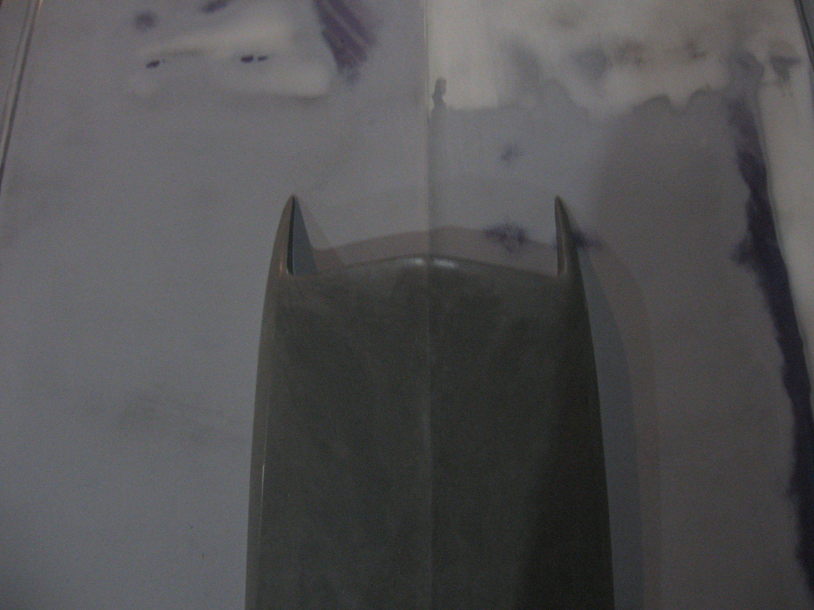
I then taped a piece of string to each end of the hood so it ran tightly right down the center ridge of the hood much like you would do with a chalk line.  This is to help me keep my center.
I then lifted up the string and slid the scoop underneath so the string ran along the center ridge of the scoop.  This will allow  me to keep it perfectly centered on the hood.

I traced around the outside of each stud to mark my hole locations.

I then began drilling, starting with a small bit and stepping my way up to a final hole size of 5/16" through 4 series of drill bit size increases.  It's essential to use a sharp bit here; the bit needs to penetrate through the metal as easily and effortlessly as possible so you don't have to distort the skin by pushing down on it with the drill.

After I finished with the 5/16" bit I did a test fit of the hood and then hogged out some of the holes with a Dremel in the direction I needed to go to make the studs fit in the hole.  By the way, if you don't have a Dremel in your body work toolbox you really need one.
All the holes are drilled now.  You can see my big ugly hole on the bottom left (I realize that did not sound right).  The next picture explains how I got that boo boo.

Beneath the back three holes there is a substructure to the hood that you also need to drill through.  After drilling all the holes on top, I went back with a small drill bit straight down through the back three holes to drill through the substructure underneath, also stepping my way up through incremental drill  bit sizes.  These holes on the bottom need to be large enough that you can fit a 10 mm deepwell socket into them to tighten the nut on the stud.  Once you've drilled them through with the 5/16" bit from the top, do not do like me and flip the hood over and try to enlarge the hole with a half inch drill bit.  On my first hole, the drill bit pushed all the way down through the skin of the hood and turned my 5/16" hole on the top of the hood into an ugly, broken 1/2" hole!  (To remedy this I will slide a rubber washer up the stud once the scoop is in place, then add the nut.)

Set the scoop in place and GENTLY tighten down the nuts from underneath.  Hand tighten them; if you over tighten them you can rip the studs out of their fragile fiberglass bosses.  I used a 10 mm deepwell socket on an extension to add the nuts to the back three studs.

Bodywork to the scoop is now needed (more on this later when I begin this), but now the scoop is installed!


Tuesday, March 27, 2012

Test fit of the valances

I finally blocked the rear valance down and got it 'good enough' (I'm not going to lie, I am not excessively picky about the valance being perfectly flat).  The most important part was to get them initially fitted to the car so I know they will go on when I'm getting ready for paint.

1. Rear valance

The rear valance was an 'improved tooling' piece I got through National Parts Depot.  It was supposed to be a better fit and have thicker metal than the other reproductions.  I got a GT valance with dual exhaust cut outs.  It's definitely wide enough and the fit isn't too bad on the passenger's side.  However, on the driver's side there is quite a gap between the valance and the rear of the quarter that is resulting from the valance having too much of an outward bow and not sitting flat enough.  I know if I try to flatten it I'm only going to create more problems than I'm trying to fix, so I'm currently contemplating just living with it.  I'm too the point where I want to finish this car the best I can but at the same time I'd like to be able to drive it before I die.

The gap on the driver's side isn't a game breaker gap but not necessarily something to be proud of either.

This is the best view of the mounted valance I could get since the back of the car is near the wall.

The passenger's side goes on quite nicely.

2.  Front valance

The front valance was one of those $33 reproduction cheapies I bought 3 or 4 years ago when I first bought the car and had no idea how in depth I would be going.  At that point I just wanted to start spending money on it.  Oh young love.  I had some oil can popping on it that I removed through a series of shrinks consisting of about 6 contacts with my stud welder.  I was ready for the fit of this thing to be an absolute joke.  I was absolutely ready to toss it in the junk and order an actual good one.  I'll be damned if this thing didn't go on almost as perfect as the Lord had intended it to.


I didn't put it on 100%, but enough to know that I wasn't in for any serious trouble, and certainly nothing that won't be fixed with some minor massaging.  The fenders aren't even mounted on all the way so I can't expect the front to fit absolutely flawlessly.  Though as you can see here it's not near as bad as one would expect.

The driver's side looks a little funky in this pic but I think it's the angle.  It was flush with the fender.


Monday, March 26, 2012

Upper control arms: [Shelby] Drop em if you got em

Today is as fine a day as any to discuss the 1" Shelby drop of the upper control arms I just completed.  It is an incredibly simple task, you just need a few items beyond your basic tools to get started.

First, order a metal template for the new holes to drill; I got mine from a guy who sells them on Ebay...it's a real nice template.  Alternatively you can get one from the guy at Daze suspension but I don't think it's as nice though it still gets the job done.  You'll also need a 17/32" drill bit.  It's an odd size but I've seen them at Sears, True Value, and of course, Ebay.  Just make sure you get one with a reduced shank to 3/8".  Mine was a 1/2" shank so I had to borrow a 1/2" chuck drill.  It stopped the project until I secured one and was annoying to say the least.  Do you know how many people DON'T have 1/2" drills?  Third, go to your favorite auto parts store and get a loaner spring compressor, but get the 'OEM style,' these have two hooks at the top and a large two-pronged fork that goes at the bottom of the spring.  Do not get a MacPherson strut spring compressor, or any kind of an an external spring compressor, or even the internal spring compressors with two hooks on the top and bottom; these bottom out on the spring perches.


The car is resting on jackstands and I've removed the shock tower cap and shock.  I have the spring compressor in place and am ready to begin wrenching on the nut at the bottom of the compressor to slowly compress the spring.

The spring is now removed.

This is a better picture of how the compressor tool is seated in the spring.  These are Grab a Trak 1" lowering 620's.  Handle this loaded spring like a BOMB.

I set it on the ground, stand off to the side, and keep my hands off to the side when decompressing so I'm out of the way if it were to pop loose.


Ball joint separator.  Toss the pickle fork unless you want to ruin your boot AND your ball joint.  The upper control arm needs to be removed and this contraption will be necessary to separate the upper balljoint from the spindle.  You can make nicer ones as I eventually will, or get a loaner tool from the auto parts store, but I was in a pinch and this demonstrates how you can scrap something together in a pinch to make your own homebrew balljoint separator tool.  I took a 3 or 4" bolt I had (don't remember the length), threaded a nut down on it, place a washer on top of that, and then a socket that will fit over the bolt threads.  The hex head of this bolt sits on the stud to the lower ball joint.  Thread the castelated nut on the upper  ball joint stud so the nut is flush with the bottom of the stud; the socket will rest against the bottom of this nut.  Now hold either the bolt head or the nut stationary with a wrench.  Whichever one is being held stationary, turn the other one such that the nut moves up the threads of the bolt.  This pushes up on the socket creating an elongating bar between the upper and lower ball joints.  Since the lower is bolted on and the upper isn't, the only one to break free is the upper.  Eventually it will pop loose and you've safely freed the spindle of the upper  ball joint.

Now take the bushing shaft, slide the template over the studs, and bolt it back to its original location in the shock tower.  You can see the small holes in the template right beneath the shaft which is where I'll start drilling for the drop.

Start with a small drill bit and slowly work your way up through sizes.  I think I stepped up through 5 sizes or so to get to a half inch hole, lubricating my drill bits frequently with motor oil.  Not only does this save your bits, it also makes it easier to keep the bit centered in the hole so you don't shift the hole over.  I was using high quality DeWalt drill bits, but still burned through my half inch bit before I even got the four new holes drilled in their entirety.  I had to go buy a second bit.  Finally finish the holes off with the 17/32" bit.  The bushing shaft studs will not fit through the hole if you try to leave it at 1/2", and even if you can get them through it won't be without damage to the threads.  You really need the 17/32" bit.  And be prepared for them to be a little spendy ($12 for the bit).  Now the second pair of holes are drilled exactly 1 inch below the originals.
While I had the upper control arms out I took the opportunity to tack weld the bushings to the housing.  I was originally planning on replacing both of the UCA's  because they were stripped out...a real bummer considering I had completely blasted them down and painted them (see Suspens(ion)ful entry a few years back), as well as replaced the ball joint with new Moogs, replaced the bushing in the spring perch, and replaced the UCA bushing shaft.

The control arms are bolted in place into their new location, 1" lower.  Torque the nuts on the shock tower to 90 ft-lbs.  Now I'll enjoy the significantly better handling, yet never know how much better it actually is since I have never driven this car.  Once I get the springs and shocks back in this will be complete.