Thursday, April 5, 2012

Bolting on a hood scoop

Having a hood scoop on my car is something I've always dreamed of, and certainly one of the first things that went on my list of 'must haves' when I originally bought this Mustang.  Going on four years now I've dreamed of what my scooped hood would look like, so while CJ's had this Dynacorn 69 Mach 1 hood scoop on sale for 20% off, I jumped on the opportunity to finally make it happen.  After all, the timing was growing essential since I am currently doing the body work on the hood.While this hood scoop was originally for 69 Mach 1's, it is essentially the same scoop you'd find on a 68 428 Cobra jet, though the bolt holes are different.  Nevertheless I have a friend who installed one of these scoops on his 67 as well, and the scoop will fit on just fine.    It was nice to finally do a 'fun' thing to the restoration.  You all know what it's like; you have the the list of absolute essentials you have to do....take off old undercoating, add new caulk, or in my case, day in and day out of  body work, applying filler, and sanding filler and primer.  And then you have that list of the really 'fun' things you want to do...the often 'non-essentials' to performance of the car, and serve no other purpose other than to make the ride look neat.  I'm rambling now so I'm going to stop.

I bought this hood scoop template on Ebay for a grand total of $3 shipped.

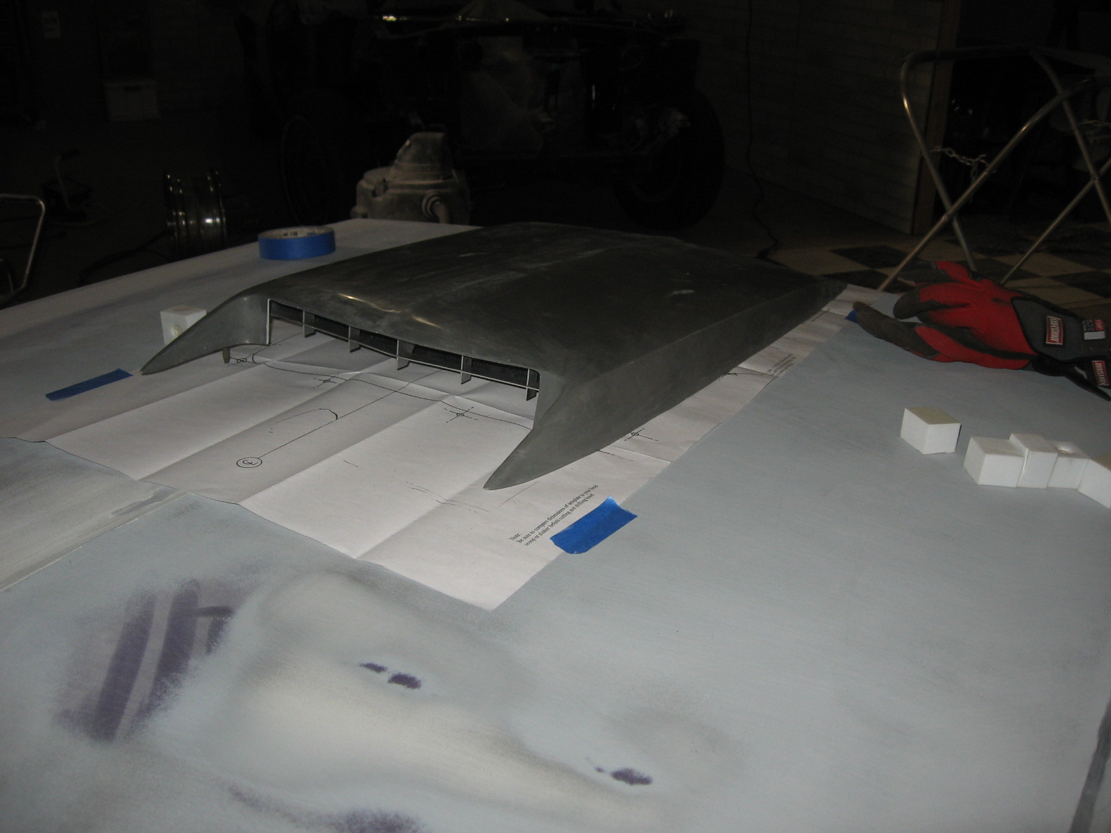
Rather than blindly sticking the template down and drilling holes, I did a test to see how well they matched up with the bolts on my Dynacorn fiberglass reproduction hood scoop.  Turns out it was a good thing I did a test fit because there were several studs that were way off.


I taped the template down so I could still get proper placement of the scoop.  The back three bolts lined up with the holes so I still used those holes in the template to make my mark on the hood for the back three bolts.

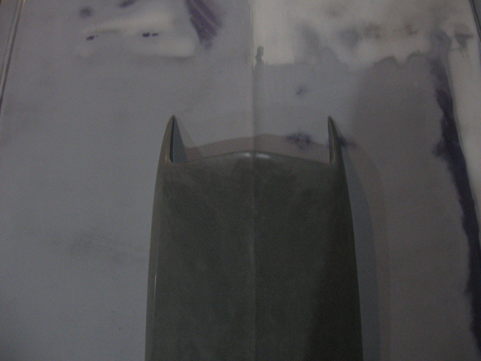
I then taped a piece of string to each end of the hood so it ran tightly right down the center ridge of the hood much like you would do with a chalk line.  This is to help me keep my center.
I then lifted up the string and slid the scoop underneath so the string ran along the center ridge of the scoop.  This will allow  me to keep it perfectly centered on the hood.

I traced around the outside of each stud to mark my hole locations.

I then began drilling, starting with a small bit and stepping my way up to a final hole size of 5/16" through 4 series of drill bit size increases.  It's essential to use a sharp bit here; the bit needs to penetrate through the metal as easily and effortlessly as possible so you don't have to distort the skin by pushing down on it with the drill.

After I finished with the 5/16" bit I did a test fit of the hood and then hogged out some of the holes with a Dremel in the direction I needed to go to make the studs fit in the hole.  By the way, if you don't have a Dremel in your body work toolbox you really need one.
All the holes are drilled now.  You can see my big ugly hole on the bottom left (I realize that did not sound right).  The next picture explains how I got that boo boo.

Beneath the back three holes there is a substructure to the hood that you also need to drill through.  After drilling all the holes on top, I went back with a small drill bit straight down through the back three holes to drill through the substructure underneath, also stepping my way up through incremental drill  bit sizes.  These holes on the bottom need to be large enough that you can fit a 10 mm deepwell socket into them to tighten the nut on the stud.  Once you've drilled them through with the 5/16" bit from the top, do not do like me and flip the hood over and try to enlarge the hole with a half inch drill bit.  On my first hole, the drill bit pushed all the way down through the skin of the hood and turned my 5/16" hole on the top of the hood into an ugly, broken 1/2" hole!  (To remedy this I will slide a rubber washer up the stud once the scoop is in place, then add the nut.)

Set the scoop in place and GENTLY tighten down the nuts from underneath.  Hand tighten them; if you over tighten them you can rip the studs out of their fragile fiberglass bosses.  I used a 10 mm deepwell socket on an extension to add the nuts to the back three studs.

Bodywork to the scoop is now needed (more on this later when I begin this), but now the scoop is installed!


Tuesday, March 27, 2012

Test fit of the valances

I finally blocked the rear valance down and got it 'good enough' (I'm not going to lie, I am not excessively picky about the valance being perfectly flat).  The most important part was to get them initially fitted to the car so I know they will go on when I'm getting ready for paint.

1. Rear valance

The rear valance was an 'improved tooling' piece I got through National Parts Depot.  It was supposed to be a better fit and have thicker metal than the other reproductions.  I got a GT valance with dual exhaust cut outs.  It's definitely wide enough and the fit isn't too bad on the passenger's side.  However, on the driver's side there is quite a gap between the valance and the rear of the quarter that is resulting from the valance having too much of an outward bow and not sitting flat enough.  I know if I try to flatten it I'm only going to create more problems than I'm trying to fix, so I'm currently contemplating just living with it.  I'm too the point where I want to finish this car the best I can but at the same time I'd like to be able to drive it before I die.

The gap on the driver's side isn't a game breaker gap but not necessarily something to be proud of either.

This is the best view of the mounted valance I could get since the back of the car is near the wall.

The passenger's side goes on quite nicely.

2.  Front valance

The front valance was one of those $33 reproduction cheapies I bought 3 or 4 years ago when I first bought the car and had no idea how in depth I would be going.  At that point I just wanted to start spending money on it.  Oh young love.  I had some oil can popping on it that I removed through a series of shrinks consisting of about 6 contacts with my stud welder.  I was ready for the fit of this thing to be an absolute joke.  I was absolutely ready to toss it in the junk and order an actual good one.  I'll be damned if this thing didn't go on almost as perfect as the Lord had intended it to.


I didn't put it on 100%, but enough to know that I wasn't in for any serious trouble, and certainly nothing that won't be fixed with some minor massaging.  The fenders aren't even mounted on all the way so I can't expect the front to fit absolutely flawlessly.  Though as you can see here it's not near as bad as one would expect.

The driver's side looks a little funky in this pic but I think it's the angle.  It was flush with the fender.


Monday, March 26, 2012

Upper control arms: [Shelby] Drop em if you got em

Today is as fine a day as any to discuss the 1" Shelby drop of the upper control arms I just completed.  It is an incredibly simple task, you just need a few items beyond your basic tools to get started.

First, order a metal template for the new holes to drill; I got mine from a guy who sells them on Ebay...it's a real nice template.  Alternatively you can get one from the guy at Daze suspension but I don't think it's as nice though it still gets the job done.  You'll also need a 17/32" drill bit.  It's an odd size but I've seen them at Sears, True Value, and of course, Ebay.  Just make sure you get one with a reduced shank to 3/8".  Mine was a 1/2" shank so I had to borrow a 1/2" chuck drill.  It stopped the project until I secured one and was annoying to say the least.  Do you know how many people DON'T have 1/2" drills?  Third, go to your favorite auto parts store and get a loaner spring compressor, but get the 'OEM style,' these have two hooks at the top and a large two-pronged fork that goes at the bottom of the spring.  Do not get a MacPherson strut spring compressor, or any kind of an an external spring compressor, or even the internal spring compressors with two hooks on the top and bottom; these bottom out on the spring perches.


The car is resting on jackstands and I've removed the shock tower cap and shock.  I have the spring compressor in place and am ready to begin wrenching on the nut at the bottom of the compressor to slowly compress the spring.

The spring is now removed.

This is a better picture of how the compressor tool is seated in the spring.  These are Grab a Trak 1" lowering 620's.  Handle this loaded spring like a BOMB.

I set it on the ground, stand off to the side, and keep my hands off to the side when decompressing so I'm out of the way if it were to pop loose.


Ball joint separator.  Toss the pickle fork unless you want to ruin your boot AND your ball joint.  The upper control arm needs to be removed and this contraption will be necessary to separate the upper balljoint from the spindle.  You can make nicer ones as I eventually will, or get a loaner tool from the auto parts store, but I was in a pinch and this demonstrates how you can scrap something together in a pinch to make your own homebrew balljoint separator tool.  I took a 3 or 4" bolt I had (don't remember the length), threaded a nut down on it, place a washer on top of that, and then a socket that will fit over the bolt threads.  The hex head of this bolt sits on the stud to the lower ball joint.  Thread the castelated nut on the upper  ball joint stud so the nut is flush with the bottom of the stud; the socket will rest against the bottom of this nut.  Now hold either the bolt head or the nut stationary with a wrench.  Whichever one is being held stationary, turn the other one such that the nut moves up the threads of the bolt.  This pushes up on the socket creating an elongating bar between the upper and lower ball joints.  Since the lower is bolted on and the upper isn't, the only one to break free is the upper.  Eventually it will pop loose and you've safely freed the spindle of the upper  ball joint.

Now take the bushing shaft, slide the template over the studs, and bolt it back to its original location in the shock tower.  You can see the small holes in the template right beneath the shaft which is where I'll start drilling for the drop.

Start with a small drill bit and slowly work your way up through sizes.  I think I stepped up through 5 sizes or so to get to a half inch hole, lubricating my drill bits frequently with motor oil.  Not only does this save your bits, it also makes it easier to keep the bit centered in the hole so you don't shift the hole over.  I was using high quality DeWalt drill bits, but still burned through my half inch bit before I even got the four new holes drilled in their entirety.  I had to go buy a second bit.  Finally finish the holes off with the 17/32" bit.  The bushing shaft studs will not fit through the hole if you try to leave it at 1/2", and even if you can get them through it won't be without damage to the threads.  You really need the 17/32" bit.  And be prepared for them to be a little spendy ($12 for the bit).  Now the second pair of holes are drilled exactly 1 inch below the originals.
While I had the upper control arms out I took the opportunity to tack weld the bushings to the housing.  I was originally planning on replacing both of the UCA's  because they were stripped out...a real bummer considering I had completely blasted them down and painted them (see Suspens(ion)ful entry a few years back), as well as replaced the ball joint with new Moogs, replaced the bushing in the spring perch, and replaced the UCA bushing shaft.

The control arms are bolted in place into their new location, 1" lower.  Torque the nuts on the shock tower to 90 ft-lbs.  Now I'll enjoy the significantly better handling, yet never know how much better it actually is since I have never driven this car.  Once I get the springs and shocks back in this will be complete.

Sunday, December 25, 2011

Body work on the bolt-ons.

Christmas Day post #2, getting some catch-up on.  Before breaking (moving) for the summer, I worked on the driver's door, the hood, and re-worked the driver's fender.  I also epoxied all the parts that bolt on, such as the valances (both front and rear), the headlight buckets, the trunk lid, and the quarter panel extensions.

I. Driver's side fender.

These were the scope of my efforts in the summer of 2010.  I was new to body work when doing this.  Since I had improved considerably over time with additional practice and experience, I was no longer happy with the work I had originally done on these fenders, not to mention I had better tools now, such as my durablocks.

After already spending countless hours on the fender, I ended up taking most of the filler off I had applied previously so I could bump the low spots out.  Since I'm much better at bumping now it was well worth the effort because I ended up with a very straight fender with considerably less filler on it.  Here the bullseye pick was a lifesaver to assist with bumping out quarter-sized low spots on the top of the fender. 

When I took the fenders out of storage, I blocked them with my durablocks to see how far off from a thorough job I really was.  It was at this time I also removed much of the filler, bumped, and reapplied.  Here my Platinum was a major advantage over the heavy-building, poor-sanding cheap 3M lightweight filler I was using.  I shot another three coats of 2k primer on the fender, then blocked and bumped.  The very last step was to fill in every tiny scratch and imperfection with EZ Sand putty.  Before moving I put three last coats of 2k on and left unsanded.
Stripping the problem areas back off the fender

Blocking the fender

Filling in imperfections, pinholes, and scratches with glazing putty before the final coats of 2k
II. Hood

The hood was a reproduction because it had e-coat on the underside.  I washed the hood off and it looked pretty straight.

I sanded to bare metal in one spot to see how many layers it had.  Confirming my suspicions, it only had a layer of the e-coat, a gray primer, and the blue and purple pearl base coats.

The hood was DA'd with 80 grit then 180 to remove the clear coat and scuff the surface.

The hood was shot with 2 coats of epoxy and then blocked, which is how it remains.
III.  Driver's side door
The paint was stripped from the door.  The handle and lock were eventually removed.

The inside of the door needed some work, first.  Such as removal of the giant mouse nest inside.

The mouse nest was cleaned out and the rust was removed with an angle grinder and cleaned up with zinc phosphate.


The door de-rusted and ready for coating with some Eastwood Rust Encapsulator, though I don't have high expectations for it working well.

There were some holes in the door just to the left of the door handle that were from pulling a dent out back in the days before stud welders were a great idea.


The holes were welded shut.  Of course this caused some distortion, which was fine because the entire area was low anyways.  This was pushed out somewhat with a pry bar.


The welds were filled first with fiberglass filler, then with 3M lightweight filler.  Additional low spots on the door were filled, but the low spots were minor.

The door was shot with two coats of epoxy and ready to be blocked.
IV.  Priming bolt-ons and pot metal.


||: Blocking and priming :||


It's Christmas Day, and since we're in Michigan alone there's nothing to do and I'm quite bored.  So I'm going to blog.  There are a few areas left that I need to catch up on.  I actually started this entry back on Sept 26 and am just now getting around to posting it.  This will  be a boring entry because I never had my camera with me when I was blocking the car.  Probably because it wasn't much to look at, and it's what I spent the entire summer doing.

The purpose of this entry is to discuss what happens after the initial two coats of epoxy are laid down.  Because I'd rather fill over epoxy than the 2k high build primer, I guide coated the epoxy and blocked it to reveal the low spots.  Many of them I bumped out, some I filled to perfection.  At this point I wised up and skim coated large panel areas to give me something to work with and create a flatter surface.

After the filler work on the epoxy was completed, I shot 1-2 coats of epoxy again, and then it was time to spray SPI 2k primer, aka high build primer.  This goes on 3 coats at a time, flashing for 5 minutes between each coat.  By the way, what I describe in this very post is what I did the entire summer.  After the final coat was flashed and dried, I blocked the panel, once again bumping out what low spots I could or filling them, this time using polyester Marston Platinum filler; equivalent in all aspects to Rage Xtreme, but at a fraction of the cost.  Polyester filler can go over almost any top coat (which is why I selected it), but it's also much creamier than your normal talc-based fillers, not to mention it sands much better, making it ideal for skimming entire panels where a very fine, light, easy sanding coat is desired to remove any last waves.  Before shooting anymore 2k, I used the opportunity to guide coat the new area and block it down.  If there were low spots I'd gently bump it from the back or spot-apply more filler.  Finally, at the edges and where deep sanding scratches are present, I skim with polyester putty, or Evercoat EZ Sand, to be exact.  The polyester and EZ sand are both being sanded with 180-220.  When I feel it's perfect I'm ready to shoot another 3 coats of 2k and block again.  Hopefully after blocking I get a flat surface.

Before closing up shop in the face of the move, one of the last things I did was put [hopefully] the final three coats of 2k down on the roof and trunk.  I left it unsanded since those panels will be setting as-is for half a year or more.